Welcome to OpenGL
This tutorial is an adaptation of https://learnopengl.com/ to use Java instead of C++. The majority of the credit for this tutorial should go to the author of the original tutorial and the other contributors.
By this moment, only the first several chapters (from setting up environment to the first triangle) are ported. This should be adequate for you to get started with OpenGL in Java with vulkan4j ecosystem. After finishing these chapters, you can continue with the original tutorial while using vulkan4j as a Java binding for OpenGL.
The rest part of the tutorial will be ported in the future, so stay tuned!
Welcome to the online book for learning OpenGL! Whether you are trying to learn OpenGL for academic purposes, to pursue a career or simply looking for a hobby, this book will teach you the basics, the intermediate, and all the advanced knowledge using modern (core-profile) OpenGL. The aim of LearnOpenGL is to show you all there is to modern OpenGL in an easy-to-understand fashion with clear examples, while also providing a useful reference for later studies.
So why read these chapters?
Throughout the internet there are thousands of documents, books, and resources on learning OpenGL, however, most of these resources are only focused on OpenGL's immediate mode (commonly referred to as the old OpenGL), are incomplete, lack proper documentation, or are not suited for your learning preferences. Therefore, my aim is to provide a platform that is both complete and easy to understand.
If you enjoy reading content that provides step-by-step instructions, clear examples, and that won't throw you in the deep with millions of details, this book is probably for you. The chapters aim to be understandable for people without any graphics programming experience, but are still interesting to read for the more experienced users. We also discuss practical concepts that, with some added creativity, could turn your ideas into real 3D applications. If all of the previous sounds like someone that could be you, then by all means, please continue.
What will you learn?
The focus of these chapters are on Modern OpenGL. Learning (and using) modern OpenGL requires a strong knowledge of graphics programming and how OpenGL operates under the hood to really get the best of your experience. So we will start by discussing core graphics aspects, how OpenGL actually draws pixels to your screen, and how we can leverage that knowledge to create some funky looking effects.
On top of the core knowledge we will discuss many useful techniques that you can use for your applications, like: traversing a scene, create beautiful lighting, load custom-made objects from a modelling program, do cool post-processing techniques, and much more. We also feature a walkthrough series where we actually create a small game based on our obtained OpenGL knowledge, so you will really get a feel of what it's like to actually do graphics programming.
Where to start
Learn OpenGL is free, and will always be free, for anyone who wants to start with graphics programming. All content is available here at the menu to your left. Simply hit the Introduction button and you're ready to start your journey!
OpenGL
Before starting our journey we should first define what OpenGL actually is. OpenGL is mainly considered an API (an Application Programming Interface) that provides us with a large set of functions that we can use to manipulate graphics and images. However, OpenGL by itself is not an API, but merely a specification, developed and maintained by the Khronos Group.
The OpenGL specification specifies exactly what the result/output of each function should be and how it should perform. It is then up to the developers implementing this specification to come up with a solution of how this function should operate. Since the OpenGL specification does not give us implementation details, the actual developed versions of OpenGL are allowed to have different implementations, as long as their results comply with the specification (and are thus the same to the user).
The people developing the actual OpenGL libraries are usually the graphics card manufacturers. Each graphics card that you buy supports specific versions of OpenGL which are the versions of OpenGL developed specifically for that card (series). When using an Apple system the OpenGL library is maintained by Apple themselves and under Linux there exists a combination of graphic suppliers' versions and hobbyists' adaptations of these libraries. This also means that whenever OpenGL is showing weird behavior that it shouldn't, this is most likely the fault of the graphics cards manufacturers (or whoever developed/maintained the library).
Since most implementations are built by graphics card manufacturers, whenever there is a bug in the implementation this is usually solved by updating your video card drivers; those drivers include the newest versions of OpenGL that your card supports. This is one of the reasons why it's always advised to occasionally update your graphic drivers.
Khronos publicly hosts all specification documents for all the OpenGL versions. The interested reader can find the OpenGL specification of version 3.3 (which is what we'll be using) here which is a good read if you want to delve into the details of OpenGL (note how they mostly just describe results and not implementations). The specifications also provide a great reference for finding the exact workings of its functions.
Core-profile vs Immediate mode
In the old days, using OpenGL meant developing in immediate mode (often referred to as the fixed function pipeline) which was an easy-to-use method for drawing graphics. Most of the functionality of OpenGL was hidden inside the library and developers did not have much control over how OpenGL does its calculations. Developers eventually got hungry for more flexibility and over time the specifications became more flexible as a result; developers gained more control over their graphics. The immediate mode is really easy to use and understand, but it is also extremely inefficient. For that reason the specification started to deprecate immediate mode functionality from version 3.2 onwards and started motivating developers to develop in OpenGL's core-profile mode, which is a division of OpenGL's specification that removed all old deprecated functionality.
When using OpenGL's core-profile, OpenGL forces us to use modern practices. Whenever we try to use one of OpenGL's deprecated functions, OpenGL raises an error and stops drawing. The advantage of learning the modern approach is that it is very flexible and efficient. However, it's also more difficult to learn. The immediate mode abstracted quite a lot from the actual operations OpenGL performed and while it was easy to learn, it was hard to grasp how OpenGL actually operates. The modern approach requires the developer to truly understand OpenGL and graphics programming and while it is a bit difficult, it allows for much more flexibility, more efficiency and most importantly: a much better understanding of graphics programming.
This is also the reason why this book is geared at core-profile OpenGL version 3.3. Although it is more difficult, it is greatly worth the effort.
As of today, higher versions of OpenGL are available to choose from (at the time of writing 4.6) at which you may ask: why do I want to learn OpenGL 3.3 when OpenGL 4.6 is out? The answer to that question is relatively simple. All future versions of OpenGL starting from 3.3 add extra useful features to OpenGL without changing OpenGL's core mechanics; the newer versions just introduce slightly more efficient or more useful ways to accomplish the same tasks. The result is that all concepts and techniques remain the same over the modern OpenGL versions so it is perfectly valid to learn OpenGL 3.3. Whenever you're ready and/or more experienced you can easily use specific functionality from more recent OpenGL versions.
When using functionality from the most recent version of OpenGL, only the most modern graphics cards will be able to run your application. This is often why most developers generally target lower versions of OpenGL and optionally enable higher version functionality.
In some chapters you'll find more modern features which are noted down as such.
Extensions
A great feature of OpenGL is its support of extensions. Whenever a graphics company comes up with a new technique or a new large optimization for rendering this is often found in an extension implemented in the drivers. If the hardware an application runs on supports such an extension the developer can use the functionality provided by the extension for more advanced or efficient graphics. This way, a graphics developer can still use these new rendering techniques without having to wait for OpenGL to include the functionality in its future versions, simply by checking if the extension is supported by the graphics card. Often, when an extension is popular or very useful it eventually becomes part of future OpenGL versions.
The developer has to query whether any of these extensions are available before using them (or use an OpenGL extension library). This allows the developer to do things better or more efficient, based on whether an extension is available:
if (GL_ARB_extension_name) {
    // Do cool new and modern stuff supported by hardware
} else {
    // Extension not supported: do it the old way
}
With OpenGL version 3.3 we rarely need an extension for most techniques, but wherever it is necessary proper instructions are provided.
State machine
OpenGL is by itself a large state machine: a collection of variables that define how OpenGL should currently operate. The state of OpenGL is commonly referred to as the OpenGL context. When using OpenGL, we often change its state by setting some options, manipulating some buffers and then render using the current context.
Whenever we tell OpenGL that we now want to draw lines instead of triangles for example, we change the state of OpenGL by changing some context variable that sets how OpenGL should draw. As soon as we change the context by telling OpenGL it should draw lines, the next drawing commands will now draw lines instead of triangles.
When working in OpenGL we will come across several state-changing functions that change the context and several state-using functions that perform some operations based on the current state of OpenGL. As long as you keep in mind that OpenGL is basically one large state machine, most of its functionality will make more sense.
Objects
The OpenGL libraries are written in C and allows for many derivations in other languages, but in its core it remains a C-library. Since many of C's language-constructs do not translate that well to other higher-level languages, OpenGL was developed with several abstractions in mind. One of those abstractions are objects in OpenGL.
An object in OpenGL is a collection of options that represents a subset of OpenGL's state. For example, we could have an object that represents the settings of the drawing window; we could then set its size, how many colors it supports and so on. One could visualize an object as a C-like struct:
struct object_name {
    float  option1;
    int    option2;
    char[] name;
};
Whenever we want to use objects it generally looks something like this (with OpenGL's context visualized as a large struct):
// The State of OpenGL
struct OpenGL_Context {
    ...
    object_name* object_Window_Target;
    ...
};
// create object
unsigned int objectId = 0;
glGenObject(1, &objectId);
// bind/assign object to context
glBindObject(GL_WINDOW_TARGET, objectId);
// set options of object currently bound to GL_WINDOW_TARGET
glSetObjectOption(GL_WINDOW_TARGET, GL_OPTION_WINDOW_WIDTH,  800);
glSetObjectOption(GL_WINDOW_TARGET, GL_OPTION_WINDOW_HEIGHT, 600);
// set context target back to default
glBindObject(GL_WINDOW_TARGET, 0);
This little piece of code is a workflow you'll frequently see when working with OpenGL. We first create an object and store a reference to it as an id (the real object's data is stored behind the scenes). Then we bind the object (using its id) to the target location of the context (the location of the example window object target is defined as GL_WINDOW_TARGET). Next we set the window options and finally we un-bind the object by setting the current object id of the window target to 0. The options we set are stored in the object referenced by objectId and restored as soon as we bind the object back to GL_WINDOW_TARGET.
The code samples provided so far are only approximations of how OpenGL operates; throughout the book you will come across enough actual examples.
The great thing about using these objects is that we can define more than one object in our application, set their options and whenever we start an operation that uses OpenGL's state, we bind the object with our preferred settings. There are objects for example that act as container objects for 3D model data (a house or a character) and whenever we want to draw one of them, we bind the object containing the model data that we want to draw (we first created and set options for these objects). Having several objects allows us to specify many models and whenever we want to draw a specific model, we simply bind the corresponding object before drawing without setting all their options again.
Let's get started
You now learned a bit about OpenGL as a specification and a library, how OpenGL approximately operates under the hood and a few custom tricks that OpenGL uses. Don't worry if you did not get all of it; throughout the book we'll walk through each step, and you'll see enough examples to really get a grasp of OpenGL.
Additional resources
- opengl.org: official website of OpenGL.
- OpenGL registry: hosts the OpenGL specifications and extensions for all OpenGL versions.
- docs.gl: an improvement of the official OpenGL documentation, supports OpenGL, OpenGL ES and GLSL features lookup.
Creating a window
The first thing we need to do before we start creating stunning graphics is to create an OpenGL context and an application window to draw in. However, those operations are specific per operating system and OpenGL purposefully tries to abstract itself from these operations. This means we have to create a window, define a context, and handle user input all by ourselves.
Luckily, there are quite a few libraries out there that provide the functionality we seek, some specifically aimed at OpenGL. Those libraries save us all the operation-system specific work and give us a window and an OpenGL context to render in. Some of the more popular libraries are GLUT, SDL, SFML and GLFW. On LearnOpenGL we will be using GLFW.
Feel free to try any of the other libraries, the setup for most is similar to GLFW's setup. But not all libraries have a vulkan4j ecosystem binding. vulkan4j ecosystem is somewhat designed to work with prior FFI practices (JNI + java.nio), so if you really wants a different library, you just need a little bit of work to make it work with vulkan4j.
Maven project
Create a Maven project and add the following dependencies to your pom.xml file:
<dependency>
    <groupId>club.doki7</groupId>
    <artifactId>ffm-plus</artifactId>
    <version>0.2.7</version>
</dependency>
<dependency>
    <groupId>club.doki7</groupId>
    <artifactId>opengl</artifactId>
    <version>0.4.4</version>
</dependency>
<dependency>
    <groupId>club.doki7</groupId>
    <artifactId>glfw</artifactId>
    <version>0.4.4</version>
</dependency>
<dependency>
    <groupId>org.joml</groupId>
    <artifactId>joml</artifactId>
    <version>1.10.8</version>
</dependency>
<dependency>
    <groupId>de.javagl</groupId>
    <artifactId>obj</artifactId>
    <version>0.4.0</version>
</dependency>
club.doki7.opengl is the OpenGL binding for Java, club.doki7.ffm-plus is a library that provides a thin wrapper over the Java 22 FFM APIs to make them easier and more type-safe to use. club.doki7.glfw is a Java binding for the GLFW library, which we'll use for window creation. org.joml is a math library that we'll use for vector and matrix operations. de.javagl.obj is a library for loading Wavefront OBJ files, which we'll use for loading 3D models.
GLFW setup
Unlike lwjgl-glfw and other Java bindings for GLFW, club.doki7.glfw does not come up with the native binaries.
Chuigda did not bundle the native libraries with
club.doki7.glfwbecause he doesn't know what's the best practice in Java world,definitely not because he's lazy. If you have a good idea, a pull request is always welcome.
Set up GLFW yourself
To set up GLFW yourself, you need to download the GLFW binaries for your operating system and architecture, either from the official website, or using your favorite package manager.Add commentMore actions
If you're using a package manager, all things should be set up for you automatically. However, if you're downloading the binaries manually, you'll need a bit more effort to make JVM find the native libraries. There are two ways to do this:
- Copy (or link) the native library file (
glfw3.dll) to some directory that is included byPATHenvironment variable. - Set the
java.library.pathsystem property to the directory containing the native libraries. This can be done by adding the following line to JVM arguments:-Djava.library.path=/path/to/glfw/native/libs. If you're using IDEs, you can usually set this in the run configuration. Consult your IDE documentation for more information.
In realworld production you may want to bundle the native libraries with your application (usually a JAR file), in that case you may use some solution like native-utils.
Base code
Let's start with the following code:
import club.doki7.glfw.GLFW;
import club.doki7.opengl.GL;

class Application {
    private GLFW glfw;

    public Application(GLFW glfw) {
        this.glfw = glfw;
    }

    public void run() {
    }
}

public class Main {
    public static void main(String[] args) {
    }

    private static void applicationStart(GLFW glfw) {
    }
}
Loading GLFW
Unlike in LWJGL or some other wrappers, with vulkan4j, you need to manually load both library and the library functions. If you are setting up GLFW manually:
import club.doki7.glfw.GLFWLoader;

// ...

public class Main {
    public static void main(String[] args) {
        try (ISharedLibrary libGLFW = GLFWLoader.loadGLFWLibrary()) {
            GLFW glfw = GLFWLoader.loadGLFW(libGLFW);
        }
    }
}
You may read the JavaDoc and the implementation of GLFWLoader to see how it works.
Finally, create an instance of Application and call its run method:
public class Main {
    public static void main(String[] args) {
        GLFW glfw = ...;

        Application app = new Application(glfw);
        app.run();
    }
}
Hitting the compile button shouldn't give you any errors, at which point we're set to go for the next chapter where we'll discuss how we can actually use GLFW to configure an OpenGL context and spawn a window. Be sure to check that all your include and library directories are correct and that the library names in the linker settings match the corresponding libraries.
Hello Window
Let's see if we can get GLFW up and running. First, let's initialize GLFW and instantiate the GLFW window:
public void run() {
    if (glfw.init() != GLFW.TRUE) {
        throw new RuntimeException("Failed to initialize GLFW");
    }

    glfw.windowHint(GLFW.CONTEXT_VERSION_MAJOR, 3);
    glfw.windowHint(GLFW.CONTEXT_VERSION_MINOR, 3);
    glfw.windowHint(GLFW.OPENGL_PROFILE, GLFW.OPENGL_CORE_PROFILE);
}
In the main function we first initialize GLFW with GLFW::init, after which we can configure GLFW using GLFW::windowHint. The first argument of GLFW::windowHint tells us what option we want to configure, where we can select the option from a constant class GLFWConstants. The second argument is an integer that sets the value of our option. A list of all the possible options and its corresponding values can be found at GLFW's window handling documentation. If you try to run the application now and it gives a lot of undefined reference errors it means you didn't successfully link the GLFW library.
Since the focus of this book is on OpenGL version 3.3 we'd like to tell GLFW that 3.3 is the OpenGL version we want to use. This way GLFW can make the proper arrangements when creating the OpenGL context. This ensures that when a user does not have the proper OpenGL version GLFW fails to run. We set the major and minor version both to 3. We also tell GLFW we want to explicitly use the core-profile. Telling GLFW we want to use the core-profile means we'll get access to a smaller subset of OpenGL features without backwards-compatible features we no longer need. Note that on Mac OS X you need to add glfw.windowHint(GLFW.OPENGL_FORWARD_COMPAT, GL.TRUE); to your initialization code for it to work.
Make sure you have OpenGL versions 3.3 or higher installed on your system/hardware otherwise the application will crash or display undefined behavior. To find the OpenGL version on your machine either call
glxinfoon Linux machines or use a utility like the OpenGL Extension Viewer for Windows. If your supported version is lower try to check if your video card supports OpenGL 3.3+ (otherwise it's antique) and/or update your drivers.
Next we're required to create a window object. This window object holds all the windowing data and is required by most of GLFW's other functions.
GLFWwindow window = glfw.createWindow(
        800,
        600,
        BytePtr.allocateString(Arena.global(), "LearnOpenGL"),
        null,
        null
);
if (window == null) {
    throw new RuntimeException("Failed to create GLFW window");
}
glfw.makeContextCurrent(window);
The GLFW::createWindow function requires the window width and height as its first two arguments respectively. The third argument allows us to create a name for the window; for now we call it "LearnOpenGL" but you're allowed to name it however you like. We can ignore the last 2 parameters. The function returns a GLFWwindow handle object that we'll later need for other GLFW operations. After that we tell GLFW to make the context of our window the main context on the current thread.
Loading OpenGL functions
After creating the window and thus having the OpenGL context, we can start loading the OpenGL functions. Create a private field:
private GL gl;
Then load GL functions with the GLFW provided loader function: GLFW::getProcAddress:
gl = new GL(name -> {
    try (Arena arena = Arena.ofConfined()) {
        return glfw.getProcAddress(BytePtr.allocateString(arena, name));
    }
});
Where are my compatibility profile functions?
The
GLclass only provides access to the OpenGL core profile functions, and in this tutorial we will only use these core profile functions.However, if you look
GLclass closely, you'll find it's asealedclass and its only subclass isGLCompatibility, which extendsGLand provides access to the compatibility profile functions. If you want to use the compatibility profile, you can useGLCompatibilityinstead ofGL. Remember to updateGLFW::windowHintcall to use compatibility profile instead of core profile.
Viewport
Before we can start rendering we have to do one last thing. We have to tell OpenGL the size of the rendering window so OpenGL knows how we want to display the data and coordinates with respect to the window. We can set those dimensions via the GL::viewport function:
gl.viewport(0, 0, 800, 600);
The first two parameters of GL::viewport set the location of the lower left corner of the window. The third and fourth parameter set the width and height of the rendering window in pixels, which we set equal to GLFW's window size.
We could actually set the viewport dimensions at values smaller than GLFW's dimensions; then all the OpenGL rendering would be displayed in a smaller window and we could for example display other elements outside the OpenGL viewport.
Behind the scenes OpenGL uses the data specified via
GL::viewportto transform the 2D coordinates it processed to coordinates on your screen. For example, a processed point of location(-0.5, 0.5)would (as its final transformation) be mapped to(200, 450)in screen coordinates. Note that processed coordinates in OpenGL are between-1and1so we effectively map from the range(-1 to 1)to(0, 800)and(0, 600).
However, the moment a user resizes the window the viewport should be adjusted as well. We can register a callback function on the window that gets called each time the window is resized. This resize callback function has the following prototype:
void framebuffer_resize_callback(GLFWwindow* window, int width, int height);
The framebuffer size function takes a GLFWwindow as its first argument and two integers indicating the new window dimensions. Whenever the window changes in size, GLFW calls this function and fills in the proper arguments for you to process.
glfw.setFramebufferSizeCallback(window, (_, w, h) -> gl.viewport(0, 0, w, h));
When the window is first displayed, our lambda expression gets called as well with the resulting window dimensions. For retina displays width and height will end up significantly higher than the original input values.
There are many callbacks functions we can set to register our own functions. For example, we can make a callback function to process joystick input changes, process error messages etc. We register the callback functions after we've created the window and before the render loop is initiated.
Ready your engines
We don't want the application to draw a single image and then immediately quit and close the window. We want the application to keep drawing images and handling user input until the program has been explicitly told to stop. For this reason we have to create a while loop, that we now call the render loop, that keeps on running until we tell GLFW to stop. The following code shows a very simple render loop:
while (glfw.windowShouldClose(window) == GLFW.FALSE) {
    glfw.swapBuffers(window);
    glfw.pollEvents();
}
The GLFW::windowShouldClose function checks at the start of each loop iteration if GLFW has been instructed to close. If so, the function returns true and the render loop stops running, after which we can close the application.
The GLFW::pollEvents function checks if any events are triggered (like keyboard input or mouse movement events), updates the window state, and calls the corresponding functions (which we can register via callback methods). The GLFW::swapBuffers will swap the color buffer (a large 2D buffer that contains color values for each pixel in GLFW's window) that is used to render to during this render iteration and show it as output to the screen.
Double buffer
When an application draws in a single buffer the resulting image may display flickering issues. This is because the resulting output image is not drawn in an instant, but drawn pixel by pixel and usually from left to right and top to bottom. Because this image is not displayed at an instant to the user while still being rendered to, the result may contain artifacts. To circumvent these issues, windowing applications apply a double buffer for rendering. The front buffer contains the final output image that is shown at the screen, while all the rendering commands draw to the back buffer. As soon as all the rendering commands are finished we swap the back buffer to the front buffer so the image can be displayed without still being rendered to, removing all the aforementioned artifacts.
One last thing
As soon as we exit the render loop we would like to properly clean/delete all of GLFW's resources that were allocated. We can do this via the GLFW::terminate function that we call at the end of the run function.
glfw.terminate();
This will clean up all the resources and properly exit the application. Now try to compile your application and if everything went well you should see the following output:
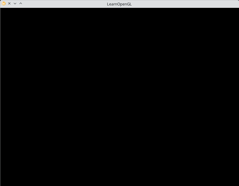
If it's a very dull and boring black image, you did things right! If you didn't get the right image or you're confused as to how everything fits together, check the full source code (and if it started flashing different colors, keep reading).
Input
We also want to have some form of input control in GLFW and we can achieve this with several of GLFW's input functions. We'll be using GLFW's GLFW::getKey function that takes the window as input together with a key. The function returns whether this key is currently being pressed. We're creating a processInput function to keep all input code organized:
private void processInput(GLFWwindow window) {
    if (glfw.getKey(window, GLFW.KEY_ESCAPE) == GLFW.PRESS) {
        glfw.setWindowShouldClose(window, GLFW.TRUE);
    }
}
Here we check whether the user has pressed the escape key (if it's not pressed, GLFW::getKey returns GLFWConstants::RELEASE). If the user did press the escape key, we close GLFW by setting its WindowShouldClose property to true using GLFW::setWindowShouldClose. The next condition check of the main while loop will then fail and the application closes.
We then call processInput every iteration of the render loop:
while (glfw.windowShouldClose(window) == GLFW.FALSE) {
    processInput(window);

    glfw.swapBuffers(window);
    glfw.pollEvents();
}
This gives us an easy way to check for specific key presses and react accordingly every frame. An iteration of the render loop is more commonly called a frame.
Rendering
We want to place all the rendering commands in the render loop, since we want to execute all the rendering commands each iteration or frame of the loop. This would look a bit like this:
while (glfw.windowShouldClose(window) == GLFW.FALSE) {
    // input
    processInput(window);

    // rendering commands here
    ...

    // check and call events and swap the buffers
    glfw.swapBuffers(window);
    glfw.pollEvents();
}
Just to test if things actually work we want to clear the screen with a color of our choice. At the start of frame we want to clear the screen. Otherwise, we would still see the results from the previous frame (this could be the effect you're looking for, but usually you don't). We can clear the screen's color buffer using glClear where we pass in buffer bits to specify which buffer we would like to clear. The possible bits we can set are GL.COLOR_BUFFER_BIT, GL.DEPTH_BUFFER_BIT and GL.STENCIL_BUFFER_BIT. Right now we only care about the color values so we only clear the color buffer.
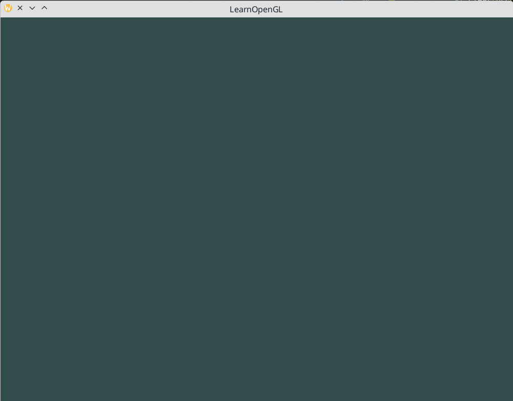
gl.clearColor(0.2f, 0.3f, 0.3f, 1.0f);
gl.clear(GL.COLOR_BUFFER_BIT);
Note that we also specify the color to clear the screen with using GL::clearColor. Whenever we call GL::clear and clear the color buffer, the entire color buffer will be filled with the color as configured by GL::clearColor. This will result in a dark green-blueish color.
As you may recall from the OpenGL chapter, the
GL::clearColorfunction is a state-setting function andGL::clearis a state-using function in that it uses the current state to retrieve the clearing color from.
So right now we got everything ready to fill the render loop with lots of rendering calls, but that's for the next chapter. I think we've been rambling long enough here.
Hello Triangle
In OpenGL everything is in 3D space, but the screen or window is a 2D array of pixels so a large part of OpenGL's work is about transforming all 3D coordinates to 2D pixels that fit on your screen. The process of transforming 3D coordinates to 2D pixels is managed by the graphics pipeline of OpenGL. The graphics pipeline can be divided into two large parts: the first transforms your 3D coordinates into 2D coordinates and the second part transforms the 2D coordinates into actual colored pixels. In this chapter we'll briefly discuss the graphics pipeline and how we can use it to our advantage to create fancy pixels.
The graphics pipeline takes as input a set of 3D coordinates and transforms these to colored 2D pixels on your screen. The graphics pipeline can be divided into several steps where each step requires the output of the previous step as its input. All of these steps are highly specialized (they have one specific function) and can easily be executed in parallel. Because of their parallel nature, graphics cards of today have thousands of small processing cores to quickly process your data within the graphics pipeline. The processing cores run small programs on the GPU for each step of the pipeline. These small programs are called shaders.
Some of these shaders are configurable by the developer which allows us to write our own shaders to replace the existing default shaders. This gives us much more fine-grained control over specific parts of the pipeline and because they run on the GPU, they can also save us valuable CPU time. Shaders are written in the OpenGL Shading Language (GLSL) and we'll delve more into that in the next chapter.
Below you'll find an abstract representation of all the stages of the graphics pipeline. Note that the blue sections represent sections where we can inject our own shaders.
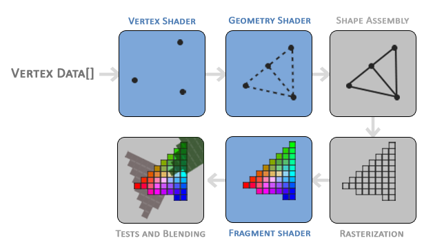
As you can see, the graphics pipeline contains a large number of sections that each handle one specific part of converting your vertex data to a fully rendered pixel. We will briefly explain each part of the pipeline in a simplified way to give you a good overview of how the pipeline operates.
As input to the graphics pipeline we pass in a list of three 3D coordinates that should form a triangle in an array here called Vertex Data; this vertex data is a collection of vertices. A vertex is a collection of data per 3D coordinate. This vertex's data is represented using vertex attributes that can contain any data we'd like, but for simplicity's sake let's assume that each vertex consists of just a 3D position and some color value.
In order for OpenGL to know what to make of your collection of coordinates and color values OpenGL requires you to hint what kind of render types you want to form with the data. Do we want the data rendered as a collection of points, a collection of triangles or perhaps just one long line? Those hints are called primitives and are given to OpenGL while calling any of the drawing commands. Some of these hints are
GL_POINTS,GL_TRIANGLESandGL_LINE_STRIP.
The first part of the pipeline is the vertex shader that takes as input a single vertex. The main purpose of the vertex shader is to transform 3D coordinates into different 3D coordinates (more on that later) and the vertex shader allows us to do some basic processing on the vertex attributes.
The output of the vertex shader stage is optionally passed to the geometry shader. The geometry shader takes as input a collection of vertices that form a primitive and has the ability to generate other shapes by emitting new vertices to form new (or other) primitive(s). In this example case, it generates a second triangle out of the given shape.
The primitive assembly stage takes as input all the vertices (or vertex if GL_POINTS is chosen) from the vertex (or geometry) shader that form one or more primitives and assembles all the point(s) in the primitive shape given; in this case two triangles.
The output of the primitive assembly stage is then passed on to the rasterization stage where it maps the resulting primitive(s) to the corresponding pixels on the final screen, resulting in fragments for the fragment shader to use. Before the fragment shaders run, clipping is performed. Clipping discards all fragments that are outside your view, increasing performance.
A fragment in OpenGL is all the data required for OpenGL to render a single pixel.
The main purpose of the fragment shader is to calculate the final color of a pixel and this is usually the stage where all the advanced OpenGL effects occur. Usually the fragment shader contains data about the 3D scene that it can use to calculate the final pixel color (like lights, shadows, color of the light and so on).
After all the corresponding color values have been determined, the final object will then pass through one more stage that we call the alpha test and blending stage. This stage checks the corresponding depth (and stencil) value (we'll get to those later) of the fragment and uses those to check if the resulting fragment is in front or behind other objects and should be discarded accordingly. The stage also checks for alpha values (alpha values define the opacity of an object) and blends the objects accordingly. So even if a pixel output color is calculated in the fragment shader, the final pixel color could still be something entirely different when rendering multiple triangles.
As you can see, the graphics pipeline is quite a complex whole and contains many configurable parts. However, for almost all the cases we only have to work with the vertex and fragment shader. The geometry shader is optional and usually left to its default shader. There is also the tessellation stage and transform feedback loop that we haven't depicted here, but that's something for later.
In modern OpenGL we are required to define at least a vertex and fragment shader of our own (there are no default vertex/fragment shaders on the GPU). For this reason it is often quite difficult to start learning modern OpenGL since a great deal of knowledge is required before being able to render your first triangle. Once you do get to finally render your triangle at the end of this chapter you will end up knowing a lot more about graphics programming.
Vertex input
To start drawing something we have to first give OpenGL some input vertex data. OpenGL is a 3D graphics library so all coordinates that we specify in OpenGL are in 3D (x, y and z coordinate). OpenGL doesn't simply transform all your 3D coordinates to 2D pixels on your screen; OpenGL only processes 3D coordinates when they're in a specific range between -1.0 and 1.0 on all 3 axes (x, y and z). All coordinates within this so called normalized device coordinates range will end up visible on your screen (and all coordinates outside this region won't).
Because we want to render a single triangle we want to specify a total of three vertices with each vertex having a 3D position. We define them in normalized device coordinates (the visible region of OpenGL) in a float array:
private static final float[] VERTICES = {
    -0.5f, -0.5f, 0.0f,
    0.5f, -0.5f, 0.0f,
    0.0f,  0.5f, 0.0f
};
Because OpenGL works in 3D space we render a 2D triangle with each vertex having a z coordinate of 0.0. This way the depth of the triangle remains the same making it look like it's 2D.
Normalized Device Coordinates (NDC)
Once your vertex coordinates have been processed in the vertex shader, they should be in normalized device coordinates which is a small space where the
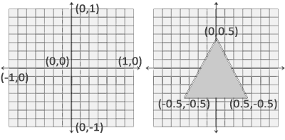
x,yandzvalues vary from-1.0to1.0. Any coordinates that fall outside this range will be discarded/clipped and won't be visible on your screen. Below you can see the triangle we specified within normalized device coordinates (ignoring the z axis):
Unlike usual screen coordinates the positive y-axis points in the up-direction and the
(0, 0)coordinates are at the center of the graph, instead of top-left. Eventually you want all the (transformed) coordinates to end up in this coordinate space, otherwise they won't be visible.Your NDC coordinates will then be transformed to screen-space coordinates via the viewport transform using the data you provided with
GL::viewport. The resulting screen-space coordinates are then transformed to fragments as inputs to your fragment shader.
With the vertex data defined we'd like to send it as input to the first process of the graphics pipeline: the vertex shader. This is done by creating memory on the GPU where we store the vertex data, configure how OpenGL should interpret the memory and specify how to send the data to the graphics card. The vertex shader then processes as many vertices as we tell it to from its memory.
We manage this memory via so-called vertex buffer objects (VBO) that can store a large number of vertices in the GPU's memory. The advantage of using those buffer objects is that we can send large batches of data all at once to the graphics card, and keep it there if there's enough memory left, without having to send data one vertex at a time. Sending data to the graphics card from the CPU is relatively slow, so wherever we can we try to send as much data as possible at once. Once the data is in the graphics card's memory the vertex shader has almost instant access to the vertices making it extremely fast
A vertex buffer object is our first occurrence of an OpenGL object as we've discussed in the OpenGL chapter. Just like any object in OpenGL, this buffer has a unique ID corresponding to that buffer, so we can generate one with a buffer ID using the GL::genBuffers function:
@Unsigned int vbo;
try(Arena arena = Arena.ofConfined()) {
    IntPtr pVBO = IntPtr.allocate(arena);
    gl.genBuffers(1, pVBO);
    vbo = pVBO.read();
}
Note: Java does not really have unsigned integers. In Java's design, signedness is associated with operations (
Integer.toStringvsInteger.toUnsignedString) rather than types. The@Unsignedannotation is used to indicate that the value should be treated as an unsigned integer, so you could remember to use unsigned series methods when dealing with them as soon as you see the annotation.
OpenGL has many types of buffer objects, and the buffer type of the vertex buffer object is GL.ARRAY_BUFFER. OpenGL allows us to bind to several buffers at once as long as they have a different buffer type. We can bind the newly created buffer to the GL.ARRAY_BUFFER target with the GL::bindBuffer function:
gl.bindBuffer(GL.ARRAY_BUFFER, vbo);
From that point on any buffer calls we make (on the GL.ARRAY_BUFFER target) will be used to configure the currently bound buffer, which is VBO. Then we can make a call to the GL::bufferData function that copies the previously defined vertex data into the buffer's memory:
gl.bufferData(
        GL.ARRAY_BUFFER,
        pVertices.segment().byteSize(),
        pVertices.segment(),
        GL.STATIC_DRAW
);
GL::bufferData is a function specifically targeted to copy user-defined data into the currently bound buffer. Its first argument is the type of the buffer we want to copy data into: the vertex buffer object currently bound to the GL.ARRAY_BUFFER target. The second argument specifies the size of the data (in bytes) we want to pass to the buffer; a simple sizeof of the vertex data suffices. The third parameter is the actual data we want to send.
The fourth parameter specifies how we want the graphics card to manage the given data. This can take 3 forms:
GL.STREAM_DRAW: the data is set only once and used by the GPU at most a few times.GL.STATIC_DRAW: the data is set only once and used many times.GL.DYNAMIC_DRAW: the data is changed a lot and used many times.
The position data of the triangle does not change, is used a lot, and stays the same for every render call so its usage type should best be GL.STATIC_DRAW. If, for instance, one would have a buffer with data that is likely to change frequently, a usage type of GL.DYNAMIC_DRAW ensures the graphics card will place the data in memory that allows for faster writes.
As of now we stored the vertex data within memory on the graphics card as managed by a vertex buffer object named VBO. Next we want to create a vertex and fragment shader that actually processes this data, so let's start building those.
Vertex shader
The vertex shader is one of the shaders that are programmable by people like us. Modern OpenGL requires that we at least set up a vertex and fragment shader if we want to do some rendering so we will briefly introduce shaders and configure two very simple shaders for drawing our first triangle. In the next chapter we'll discuss shaders in more detail.
The first thing we need to do is write the vertex shader in the shader language GLSL (OpenGL Shading Language) and then compile this shader so we can use it in our application. Below you'll find the source code of a very basic vertex shader in GLSL:
#version 330 core
layout (location = 0) in vec3 aPos;

void main() {
    gl_Position = vec4(aPos, 1.0f);
}
As you can see, GLSL looks similar to C. Each shader begins with a declaration of its version. Since OpenGL 3.3 and higher the version numbers of GLSL match the version of OpenGL (GLSL version 420 corresponds to OpenGL version 4.2 for example). We also explicitly mention we're using core profile functionality.
Next we declare all the input vertex attributes in the vertex shader with the in keyword. Right now we only care about position data so we only need a single vertex attribute. GLSL has a vector datatype that contains 1 to 4 floats based on its postfix digit. Since each vertex has a 3D coordinate we create a vec3 input variable with the name aPos. We also specifically set the location of the input variable via layout (location = 0) and you'll later see that why we're going to need that location.
Vector
In graphics programming we use the mathematical concept of a vector quite often, since it neatly represents positions/directions in any space and has useful mathematical properties. A vector in GLSL has a maximum size of 4 and each of its values can be retrieved via
vec.x,vec.y,vec.zandvec.wrespectively where each of them represents a coordinate in space. Note that thevec.wcomponent is not used as a position in space (we're dealing with 3D, not 4D) but is used for something called perspective division. We'll discuss vectors in much greater depth in a later chapter.
To set the output of the vertex shader we have to assign the position data to the predefined gl_Position variable which is a vec4 behind the scenes. At the end of the main function, whatever we set gl_Position to will be used as the output of the vertex shader. Since our input is a vector of size 3 we have to cast this to a vector of size 4. We can do this by inserting the vec3 values inside the constructor of vec4 and set its w component to 1.0f (we will explain why in a later chapter).
The current vertex shader is probably the most simple vertex shader we can imagine because we did no processing whatsoever on the input data and simply forwarded it to the shader's output. In real applications the input data is usually not already in normalized device coordinates so we first have to transform the input data to coordinates that fall within OpenGL's visible region.
Compiling a shader
We take the source code for the vertex shader and store it in a const Java string as a static final member of Application class:
private static final String VERTEX_SHADER_SOURCE =
        """
        #version 330 core
        layout (location = 0) in vec3 aPos;

        void main() {
            gl_Position = vec4(aPos, 1.0);
        }
        """;
In order for OpenGL to use the shader it has to dynamically compile it at run-time from its source code. The first thing we need to do is create a shader object, again referenced by an ID. So we store the vertex shader as an @Unsigned int and create the shader with GL::createShader:
@Unsigned int vertexShader;
vertexShader = gl.createShader(GL.VERTEX_SHADER);
We provide the type of shader we want to create as an argument to GL::createShader. Since we're creating a vertex shader we pass in GL.VERTEX_SHADER.
Next we attach the shader source code to the shader object and compile the shader:
vertexShader = gl.createShader(GL.VERTEX_SHADER);
var pVertexShaderSource = PointerPtr.allocateV(arena, BytePtr.allocateString(arena, VERTEX_SHADER_SOURCE));
gl.shaderSource(vertexShader, 1, pVertexShaderSource, null);
gl.compileShader(vertexShader);
The GL::shaderSource function takes the shader object to compile to as its first argument. The second argument specifies how many strings we're passing as source code, which is only one. The third parameter is the actual source code of the vertex shader and we can leave the 4th parameter to null.
You probably want to check if compilation was successful after the call to
GL::compileShaderand if not, what errors were found so you can fix those. Checking for compile-time errors is accomplished as follows:IntPtr pSuccess = IntPtr.allocate(arena); BytePtr infoLog = BytePtr.allocate(arena, 512); gl.getShaderiv(vertexShader, GL.COMPILE_STATUS, pSuccess);First we define an integer to indicate success and a storage container for the error messages (if any). Then we check if compilation was successful with
GL::getShaderiv. If compilation failed, we should retrieve the error message withGL::getShaderInfoLogand print the error message.if (pSuccess.read() == GL.FALSE) { gl.getShaderInfoLog(vertexShader, infoLog); throw new RuntimeException("Vertex shader compilation failed: " + infoLog.readString()); }
If no errors were detected while compiling the vertex shader it is now compiled.
Fragment shader
The fragment shader is the second and final shader we're going to create for rendering a triangle. The fragment shader is all about calculating the color output of your pixels. To keep things simple the fragment shader will always output an orange-ish color.
Colors in computer graphics are represented as an array of 4 values: the red, green, blue and alpha (opacity) component, commonly abbreviated to RGBA. When defining a color in OpenGL or GLSL we set the strength of each component to a value between
0.0and1.0. If, for example, we would set red to1.0and green to1.0we would get a mixture of both colors and get the color yellow. Given those 3 color components we can generate over 16 million different colors!
#version 330 core
out vec4 FragColor;

void main() {
    FragColor = vec4(1.0f, 0.5f, 0.2f, 1.0f);
}
The fragment shader only requires one output variable and that is a vector of size 4 that defines the final color output that we should calculate ourselves. We can declare output values with the out keyword, that we here promptly named FragColor. Next we simply assign a vec4 to the color output as an orange color with an alpha value of 1.0 (1.0 being completely opaque).
The process for compiling a fragment shader is similar to the vertex shader, although this time we use the GL.FRAGMENT_SHADER constant as the shader type:
@Unsigned int fragmentShader;
fragmentShader = gl.createShader(GL.FRAGMENT_SHADER);
var pFragmentShaderSource = PointerPtr.allocateV(arena, BytePtr.allocateString(arena, FRAGMENT_SHADER_SOURCE));
gl.shaderSource(fragmentShader, 1, pFragmentShaderSource, null);
gl.compileShader(fragmentShader);
Both the shaders are now compiled and the only thing left to do is link both shader objects into a shader program that we can use for rendering. Make sure to check for compile errors here as well!
Shader program
A shader program object is the final linked version of multiple shaders combined. To use the recently compiled shaders we have to link them to a shader program object and then activate this shader program when rendering objects. The activated shader program's shaders will be used when we issue render calls.
When linking the shaders into a program it links the outputs of each shader to the inputs of the next shader. This is also where you'll get linking errors if your outputs and inputs do not match.
Creating a program object is easy:
@Unsigned int shaderProgram;
shaderProgram = gl.createProgram();
The GL::createProgram function creates a program and returns the ID reference to the newly created program object. Now we need to attach the previously compiled shaders to the program object and then link them with GL::linkProgram:
gl.attachShader(shaderProgram, vertexShader);
gl.attachShader(shaderProgram, fragmentShader);
gl.linkProgram(shaderProgram);
The code should be pretty self-explanatory, we attach the shaders to the program and link them via GL::linkProgram.
Just like shader compilation we can also check if linking a shader program failed and retrieve the corresponding log. However, instead of using
GL::getShaderivandGL::getShaderInfoLogwe now use:gl.getProgramiv(shaderProgram, GL.LINK_STATUS, pSuccess); if (pSuccess.read() == GL.FALSE) { gl.getProgramInfoLog(shaderProgram, infoLog); throw new RuntimeException("Shader program linking failed: " + infoLog.readString()); }
The result is a program object that we can activate by calling GL::useProgram with the newly created program object as its argument:
gl.useProgram(shaderProgram);
Every shader and rendering call after GL::useProgram will now use this program object (and thus the shaders).
Oh yeah, and don't forget to delete the shader objects once we've linked them into the program object; we no longer need them anymore:
gl.deleteShader(vertexShader);
gl.deleteShader(fragmentShader);
Right now we sent the input vertex data to the GPU and instructed the GPU how it should process the vertex data within a vertex and fragment shader. We're almost there, but not quite yet. OpenGL does not yet know how it should interpret the vertex data in memory and how it should connect the vertex data to the vertex shader's attributes. We'll be nice and tell OpenGL how to do that.
Linking Vertex Attributes
The vertex shader allows us to specify any input we want in the form of vertex attributes and while this allows for great flexibility, it does mean we have to manually specify what part of our input data goes to which vertex attribute in the vertex shader. This means we have to specify how OpenGL should interpret the vertex data before rendering.
Our vertex buffer data is formatted as follows:
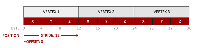
- The position data is stored as 32-bit (4 byte) floating point values.
- Each position is composed of 3 of those values.
- There is no space (or other values) between each set of 3 values. The values are tightly packed in the array.
- The first value in the data is at the beginning of the buffer.
With this knowledge we can tell OpenGL how it should interpret the vertex data (per vertex attribute) using GL::vertexAttribPointer:
gl.vertexAttribPointer(
        0,
        3,
        GL.FLOAT,
        (byte) GLFW.FALSE,
        3 * Float.BYTES,
        MemorySegment.NULL
);
gl.enableVertexAttribArray(0);
The function GL::vertexAttribPointer has quite a few parameters so let's carefully walk through them:
- The first parameter specifies which vertex attribute we want to configure. Remember that we specified the location of the
positionvertex attribute in the vertex shader withlayout (location = 0). This sets the location of the vertex attribute to0and since we want to pass data to this vertex attribute, we pass in0. - The next argument specifies the size of the vertex attribute. The vertex attribute is a
vec3so it is composed of3values. - The third argument specifies the type of the data which is
GL.FLOAT(avec*in GLSL consists of floating point values). - The next argument specifies if we want the data to be normalized. If we're inputting integer data types (int, byte) and we've set this to
GL.TRUE, the integer data is normalized to0(or-1for signed data) and1when converted to float. This is not relevant for us so we'll leave this atGL.FALSE. - The fifth argument is known as the stride and tells us the space between consecutive vertex attributes. Since the next set of position data is located exactly 3 times the size of a float away we specify that value as the stride. Note that since we know that the array is tightly packed (there is no space between the next vertex attribute value) we could've also specified the stride as
0to let OpenGL determine the stride (this only works when values are tightly packed). Whenever we have more vertex attributes we have to carefully define the spacing between each vertex attribute, but we'll get to see more examples of that later on. - The last parameter is of type
void*and thus requires the weirdMemorySegment.NULL. This is the offset of where the position data begins in the buffer. Since the position data is at the start of the data array this value is just0. We will explore this parameter in more detail later on
Each vertex attribute takes its data from memory managed by a VBO and which VBO it takes its data from (you can have multiple VBOs) is determined by the VBO currently bound to
GL.ARRAY_BUFFERwhen callingGL::vertexAttribPointer. Since the previously defined VBO is still bound before callingGL::vertexAttribPointervertex attribute0is now associated with its vertex data.
Now that we specified how OpenGL should interpret the vertex data we should also enable the vertex attribute with GL::enableVertexAttribArray giving the vertex attribute location as its argument; vertex attributes are disabled by default. From that point on we have everything set up: we initialized the vertex data in a buffer using a vertex buffer object, set up a vertex and fragment shader and told OpenGL how to link the vertex data to the vertex shader's vertex attributes. Drawing an object in OpenGL would now look something like this:
// 0. copy our vertices array into a buffer for OpenGL to use
gl.bindBuffer(GL.ARRAY_BUFFER, vbo);
gl.bufferData(
        GL.ARRAY_BUFFER,
        pVertices.segment().byteSize(),
        pVertices.segment(),
        GL.STATIC_DRAW
);

// 1. then set the vertex attribute pointers
gl.vertexAttribPointer(
        0,
        3,
        GL.FLOAT,
        (byte) GLFW.FALSE,
        3 * Float.BYTES,
        MemorySegment.NULL
);
gl.enableVertexAttribArray(0);

// 2. use our shader program when we want to render an object
gl.useProgram(shaderProgram);

// 3. now draw the object
someOpenGLFunctionThatDrawsOurTriangle();
We have to repeat this process every time we want to draw an object. It may not look like that much, but imagine if we have over 5 vertex attributes and perhaps 100s of different objects (which is not uncommon). Binding the appropriate buffer objects and configuring all vertex attributes for each of those objects quickly becomes a cumbersome process. What if there was some way we could store all these state configurations into an object and simply bind this object to restore its state?
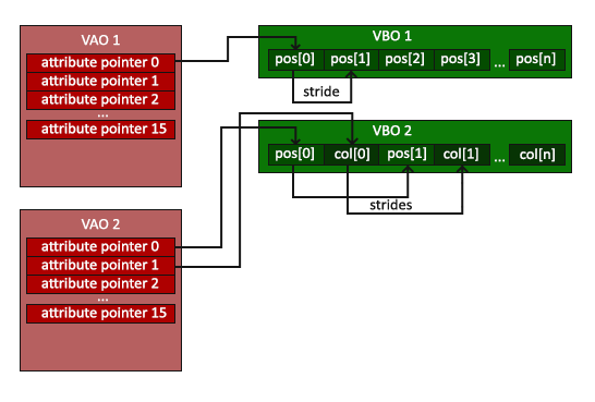
Vertex Array Object
A vertex array object (also known as VAO) can be bound just like a vertex buffer object and any subsequent vertex attribute calls from that point on will be stored inside the VAO. This has the advantage that when configuring vertex attribute pointers you only have to make those calls once and whenever we want to draw the object, we can just bind the corresponding VAO. This makes switching between different vertex data and attribute configurations as easy as binding a different VAO. All the state we just set is stored inside the VAO.
Core OpenGL requires that we use a VAO so it knows what to do with our vertex inputs. If we fail to bind a VAO, OpenGL will most likely refuse to draw anything.
A vertex array object stores the following:
- Calls to
GL::enableVertexAttribArrayorGL::disableVertexAttribArray. - Vertex attribute configurations via
GL::vertexAttribPointer. - Vertex buffer objects associated with vertex attributes by calls to
GL::vertexAttribPointer.
The process to generate a VAO looks similar to that of a VBO:
@Unsigned int vao;
@Unsigned IntPtr pVAO = IntPtr.allocate(arena);
gl.genVertexArrays(1, pVAO);
vao = pVAO.read();
To use a VAO all you have to do is bind the VAO using GL::bindVertexArray. From that point on we should bind/configure the corresponding VBO(s) and attribute pointer(s) and then unbind the VAO for later use. As soon as we want to draw an object, we simply bind the VAO with the preferred settings before drawing the object and that is it. In code this would look a bit like this:
// ..:: Initialization code (done once (unless your object frequently changes)) :: ..
// 1. bind Vertex Array Object
gl.bindVertexArray(vao);
// 2. copy our vertices array into a buffer for OpenGL to use
gl.bindBuffer(GL.ARRAY_BUFFER, vbo);
gl.bufferData(
        GL.ARRAY_BUFFER,
        pVertices.segment().byteSize(),
        pVertices.segment(),
        GL.STATIC_DRAW
);
// 3. then set our vertex attribute pointers
gl.vertexAttribPointer(
        0,
        3,
        GL.FLOAT,
        (byte) GLFW.FALSE,
        3 * Float.BYTES,
        MemorySegment.NULL
);
gl.enableVertexAttribArray(0);

[...]

// ...:: Drawing code (in render loop) :: ..
// 4. draw the object
gl.useProgram(shaderProgram);
gl.bindVertexArray(vao);
someOpenGLFunctionThatDrawsOurTriangle();
And that is it! Everything we did the last few million pages led up to this moment, a VAO that stores our vertex attribute configuration and which VBO to use. Usually when you have multiple objects you want to draw, you first generate/configure all the VAOs (and thus the required VBO and attribute pointers) and store those for later use. The moment we want to draw one of our objects, we take the corresponding VAO, bind it, then draw the object and unbind the VAO again.
The triangle we've all been waiting for
To draw our objects of choice, OpenGL provides us with the GL::drawArrays function that draws primitives using the currently active shader, the previously defined vertex attribute configuration and with the VBO's vertex data (indirectly bound via the VAO).
gl.useProgram(shaderProgram);
gl.bindVertexArray(vao);
gl.drawArrays(GL.TRIANGLES, 0, 3);
The GL::drawArrays function takes as its first argument the OpenGL primitive type we would like to draw. Since I said at the start we wanted to draw a triangle, and I don't like lying to you, we pass in GL.TRIANGLES. The second argument specifies the starting index of the vertex array we'd like to draw; we just leave this at 0. The last argument specifies how many vertices we want to draw, which is 3 (we only render 1 triangle from our data, which is exactly 3 vertices long).
Now try to compile the code and work your way backwards if any errors popped up. As soon as your application compiles, you should see the following result: